|
Replacing your window regulator and door latch assembly
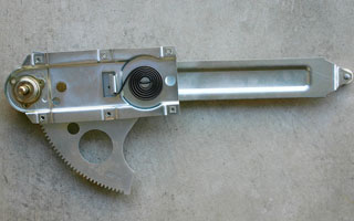
Are the door locks or latches on your late ’60s or early ’70s GM car jamming or not working altogether?
How about the windows? Do they rattle or jam in their tracks?
Maybe it’s time for a door “tune-up”.
Tools: Phillips screwdriver, impact driver (optional), hammer, socket wrenches, open-ended wrenches, window crank removal tool, white lithium grease, flashlight and small inspection mirror, window crank removal tool
Cost: Window regulator assemblies approx. $80-$100 each, door latch assemblies approx. $75 each
Tinware: Window regulator assemblies (Original Parts Group part# CH25879 right, and CH25880 left), door latch assemblies (OPGI part# C980007 right, and C980008 left)
Tip: We recommend wearing long sleeves while working inside the door assembly. Sharp edges can easily cut skin! If necessary, use flashlight and small inspection mirror to make sure that rollers are firmly set in tracks.
Before starting, roll your window to its “up” position. This will allow easy access to the inner door assemblies. Clamp the window in this position, taking care not to scratch the glass (when the window regulator assembly is removed, nothing will be supporting the glass).

To get things started, we’re going to remove the window crank with removal tool. Tool is slipped behind crank until it is pushed against retaining pin. Gently pry tool until crank is removed.
Next, we remove inner door handle. Use a 5/16” open-end wrench on single nut located under handle. Then, remove 2 screws located under molded armrest, and 2 sheetmetal screws located at bottom of door panel (in carpeted area). Pry 4 retaining clips with window crank tool, and pull panel.
Now that everything’s exposed, we’re going to remove the 3 door latch retaining screws. A #3 Phillips screwdriver can be used, but if the screws are rusted, you can easily strip the heads. We recommend an impact driver for this procedure. At this point, you should also unscrew and remove the the door lock knob, then gently pry loose the door lock ferrules (the circular trim rings around the door locks).
Using socket wrench, remove the 3 screws that retain the inner door latch mechanism. You should also inspect the control rod and the lock rod. Look for stress cracks or undue amounts of rust. If the rods appear questionable, they should be replaced.
Our control and lock rods were OK, so we attached them to the new door latch assembly. Fortunately, the rods require no screws or nuts, and should “snap” back into place. We then reinstalled the new latch assembly. Do not over tighten screws!
Now, on to the window regulator. Make sure the window is clamped (use a vise grip or other clamp) in the “up” position. (This will prevent the window from “falling” into the door when the regulator assembly is removed). Using socket wrench, remove the 4 retaining bolts that hold the front end of the regulator assembly.
Next, we are going to remove the door guide rail. The door guide rail acts as a fixed point that holds the bottom of the window regulator assembly. Very Important: Mark the location of the bolt closest to the door jamb. This bolt is adjustable, and its position is set at the factory. It is critical that the bolt be returned to its original location. Using a socket wrench, remove the 2 bolts and pull the door guide rail.
Then, reach into door cavity and work regulator assembly back and forth to remove rollers from the window roller track. This will be a tight operation, so watch those sharp metal edges!
Install new window regulator assembly. First, bend the fixed window guide rail flanges open slightly using pliers, and insert regulator roller into the window channel track. Then crimp back into original position. It may be necessary to wind the window crank to line up the 4 mounting bolt holes in the regulator assembly with the holes in the door. Using socket wrench, re-tighten all 4 bolts. Do not over tighten.
Remove clamp and gently lower window. Place door guide rail inside door, and attach “scissor” arm of regulator assembly back into door guide rail channel. Tighten bolts, making sure that rear most bolt is in its original position. Using a white lithium grease, lubricate all moving parts (window regulator, door latch, guide rollers) at their hinge points. This is done after installation to avoid getting grease all over window, door, hands, etc.
Now that that’s all taken care of, it’s time to reinstall the door panel. You can use your old door panel clips, but we’d recommend using new ones, as the originals have probably lost some of their shape and tension.
Re-attach your window cranks and inner door handle, and enjoy the fruits of your efforts!
|
 |
|
Installing a new turn signal switch and cancel cam
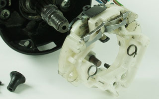
Although not a major mechanical crisis, a broken turn signal switch can be rather bothersome on a routine basis (not to mention a safety hazard). This highly important switch is responsible for activating the signal lamps at the front and the rear of the vehicle.
Along with the canceling cam, it is tightly nestled into the steering column housing just behind the center hub of the steering wheel.The turn signal lever attaches directly to the body of the switch through a small slot in the steering shroud. On the back of the switch is a series of wires and an electrical connector, which runs down the length of the steering column. The long, flat connector plugs into the under-dash wiring harness and bridges the gap between the switch and the power source. Activated by upward or downward movement of the lever, the internal switch and its contacts enable the signal lamps to be turned on and off.
Tools: steering wheel puller, standard socket set, Phillips screwdriver, flat-blade screwdriver
Cost: approximately $60-$120 depending on year and model of car
Tinware: turn signal switch assembly, canceling cam, turn signal lever (optional), dielectric grease, length of twine. OPGI stocks a wide selection of Actuating Cam/Turn Signals, as well as Canceling Cams.
Tip: When removing the old switch from the column, tie a piece of string or twine to the end of the connector. This can used to feed and guide the new harness down through the shaft cover.
Due to the excessive use of the turn signal switch, the plastic body and various actuating springs and levers are often worn down and rendered useless. Corrosion is yet another culprit in the premature failure of the switch. The dielectric grease used to lubricate and protect the contact points is commonly found contaminated, dried-up, or even burned off!
Out of sight, out of mind, right? Well, the turn signal switch is one of many overlooked components that fall into this forgotten category. But fortunately, the swap is pretty painless and only requires the removal of the steering wheel to accomplish. In fact, while you’re there, you may want to look at replacing any other suspect pieces such as the turn signal lever, horn buttons and contacts, or even the steering wheel center cap.
When working with anything remotely electrical, the first priority is to disconnect battery power from the rest of the vehicle. Grab a wrench or socket and remove the negative battery cable from its terminal post. Turning your attention to the steering wheel, carefully remove the center cap and retainer or trim pad (depending on year). Most early vehicles with a spoke-style wheel have a center emblem cap. Using a small, flat-blade screwdriver, gently pry one edge of the cap up and out of the retainer. The later, trim-pad style steering wheels are fastened by retaining screws in the backside of the wheel.
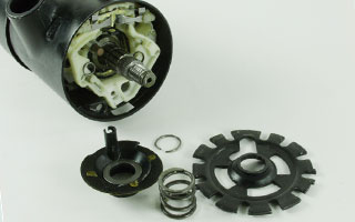
The turn signal switch assembly is a tight fit. The cancel cam, spring, and washer are held in front of the switch by the C-ring.
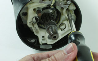
The switch is fastened to the housing by three small retaining screws.

The harness for the switch is slid down inside the steering column cover.
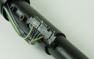
At the other end, the switch connector plugs into the under-dash wiring harness.
To remove the wheel from the steering shaft, a steering wheel puller is necessary. The puller can be found at any parts supply store and is a great tool to have available in the box. The horn ring, contacts, and retainer will first need to go in order to fully access the steering wheel nut. A small Phillips screwdriver should handle the order. Before approaching the wheel, mark the positioning in relation to the shaft. This will ensure the wheel is reinstalled correctly and straight. Remove the lock nut and washer, and pull (with the specialty tool) the wheel from the steering column shaft.
On later models, the switch assembly is secured to the shaft by a C-clip retainer. Use a compression tool to compress the lock plate and remove the C-clip. The cancel cam can be removed and replaced by hand. It simply slides down and around the shaft in front of the signal switch. Take note of the way it’s installed prior to disassembly. The turn signal lever and the four-way flasher knob (if applicable) can now be unscrewed from the body of the switch. On some automatic equipped vehicles, the transmission indicator will need to be removed as well. The switch is fastened to the steering column housing by three small retaining screws. Once the switch is loose, unplug the connector from the dash harness at the base of the steering column. It may necessary to first unbolt the column from the dash carrier. Be sure to properly support the column after removing its bracing. Do NOT allow the column to “hang” suspended by the lower support only.
To eliminate the switch from the column, the applicable column covers and housings must be removed to allow clearance for the connector to slide through. Different years and models will have similar, yet special circumstances. Carefully guide the harness and its connector body up through the column.
Reverse your steps to install the new components. Make sure the turn signal switch is in the neutral position prior to installing the cancel cam, spring, and washer. The flasher knob should be in the “out” position.
|
 |
|
Wet sanding, 101
Wet sanding a vehicle after a fresh paint job is almost always mandatory. No matter how many hours are spent prepping and sanding the body before paint, the surface of the car will take on a somewhat coarse finish after the paint has dried. Once the paint has been allowed to properly cure, the application of very fine sandpaper and water can make a huge difference in the final gloss and appearance of your machine.
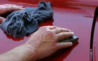
In fact, some shops make a habit out of wet-sanding their paint jobs numerous times over.
Tools: soft-block sanding pad
Cost: approximately $20 for supplies
Tinware: 1000-2000-grit fine sandpaper, garden hose or bucket, clean rags
Tip: Choose an open, outdoor area that will allow you to run water continuously for extended periods of time.
We have all seen it. A new paint job can look absolutely stunning at first glance and from a short distance away. However, after closer inspection you begin to find small, circular dimples throughout the finish that closely resemble the pitted surface of an orange peel. Bummer! Unfortunately, this is a common occurrence in the act of applying new paint. Even the veteran painters are plagued with the “orange peel” syndrome from time to time. In extreme cases, it can ruin the entire job. But most of the time, it’s easily fixable with some sandpaper and a little finesse. Starting with 1000-grit paper, they slowly and meticulously work every line and contour of the newly-skinned metal. The process may be repeated for each different grit of paper used, often times all the way up to 2000-grit. This helps knock down the “orange peel” effect and eliminate any inconsistencies in the paint. You can bet the final finish is silky smooth and nothing short of awesome!
Although the art of wet-sanding is usually practiced in the body/paint shop arena, it can effectively be used to clean stubborn residue and gunk off your car’s paint. Tree sap, bird droppings, and dead bugs can be small killers on a nice paint job. They should be removed and cleaned as soon as possible. If left on the surface, these harmful agents (not to mention unsightly) are literally baked into the paint by the sun and can leave permanent markings and discoloration. If the standard soap-and-warm-water approach fails to budge and dissolve the gunk from the paint, try using a bug and tar remover. These products can safely be used on just about any painted surface, and with positive results. After the griminess has been thoroughly cleaned off, lightly wet-sanding the area should remove any could-be lasting marks from the finish.
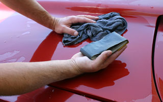
The actual task of wet-sanding is pretty painless. It does not require much force or pressure to be applied to the paint in order to smooth the finish. Working in small, light passes around the problem area tends to be the most effective method. Heavy swipes can dig into the paint and cause excess scratching. Of course, this takes more work to fix than you originally bargained for. So go slow, and take it easy.
Grab some fine wet-sandpaper in the grit of your choice (preferably between 1000 and 2000), a clean rag, and either a garden hose or a clean bucket of water. The most important thing to remember when wet-sanding is keeping the area very saturated. If the surface begins to dry out during sanding, you run the high risk of scratching and damaging the car’s paint. One way to avoid this problem is to position and secure a hose to the particular area.
Simply turn on the faucet and allow the water to continuously run over the paint and the sandpaper. If a hose is not available, a clean bucket of water and a rag will work in maintaining the desired effect. Sand a little- water a lot. Whether you have an entire body to smooth or perhaps just a small blemish, if you stick to these basic principals, the results will speak for themselves.
|
 |
|
Factory double wall exhaust “crush”
It’s hard enough to make power when you know the playing field. Fresh engine, right rear end gears, perfect transmission set up – they all contribute. But when something as simple as an exhaust pipe that appears to be fine turns out to be a major performance deterrent, that’s a tough one.
A good friend of mine had this problem with his ’69 Chevelle big block. Even with all the aforementioned goodies, the car still suffered in off-the-line get up and go. After thorough research he still couldn’t find the problem, but it was clear further investigation was required.
My buddy had put a new set of mufflers on the car a couple of years earlier. This improved the sound some, but other than “sounding” faster, it didn’t do much. He eventually purchased a complete new American Thunder Flowmaster system from OPGI part# 17119.
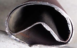
A stop by the local exhaust shop for the install netted a total change in his Chevelle’s personality. Not only did it improve the sound, but it woke up a sleeping giant. The change was remarkable and set in motion a thought that something must have been wrong with the original factory exhaust. The original system did not appear damaged by the flat spot in the double wall tubing where it tucks under the frame. That was not the case.
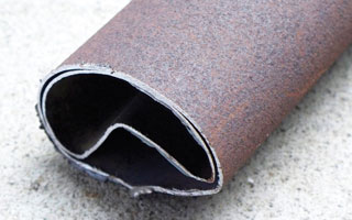
Cutting through the double wall tubing revealed an interesting problem that from further research proved to be a common problem with these exhaust configurations.
Over time, heat had caused the inner tubing to separate, reducing the overall internal flow by as much as half. In effect, the tubing is reduced to less than a one-inch diameter total area.
For anyone with a vehicle with an original style exhaust system of this type, if your vehicle is experiencing any kind of reduced power over time, this might be a good place to check. We experienced the exact same problem with our project ’69 Buick Skylark. The original exhaust system looked just fine from the outside, but it was suffering from the crushed pipe “syndrome” as well. A new exhaust system did the trick just fine. OPGI carries all exhaust system components for all GM A-body vehicles.
|
|