|
|
|
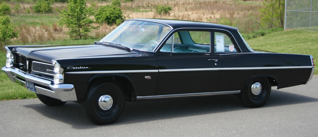
Aluma Chief Rides Again
An aging warrior is restored to glory.
by Charlie Morris
By turning a blind eye to the infamous 1957 Automobile Manufacturers Association ban on factory participation in racing, the folks at Pontiac had gained a leg up on the competition when the factories jumped back into the fray in 1960. Hired to save the faltering company in 1955, Pontiac General Manager “Bunkie” Knudsen had turned a team of engineers, known as the Super Duty Group, loose to develop Pontiac engines into world beaters. Combining their own talents with those of established manufacturers such as Mickey Thompson, the Super Duty Group transformed Pontiac into a force to be reckoned with on the dragstrip. And by the early 1960s, Pontiac became practically unbeatable in NASCAR competition.
Pontiac had also pioneered the use of lightweight components on their drag cars such as aluminum bumpers, fenders, and hoods in 1961. But by 1963, the competition had also developed lightweight cars and unitized vehicle construction. The big Pontiacs were saddled with a nearly insurmountable 300+ pound weight disadvantage. On top of that, Chrysler’s 426 Max Wedge engine made its debut...but back to that weight thing: While our feature car with all creature comforts deleted and a prodigious use of lightweight parts still comes in at 3636 pounds, the Plymouths and Dodges of the time barely tickled the scales at around 3300 pounds.
So as the sun began to set on full-sized factory drag cars, it was obvious that Pontiac’s days at the top were numbered. But even more ominous were rumblings within the division of another racing ban. That rumor came true in January, 1963, when General Motors officially ended corporate support of racing.

|
|
 Prior to the racing ban, Pontiac had rolled out some very hot offerings for 1963. This included the famous Swiss cheese Catalinas powered by the top-of-the-line 421 cube, 405 horsepower Super Duty engine and 14 similarly equipped Catalina two-door sedans...of which our feature car is one.
|
|
It’s pretty obvious that our feature car was built to race by virtue of the optional 421 Super Duty engine, electronic ignition, aluminum case Borg-Warner close ratio 4-speed transmission, Saf T Track aluminum differential (carrying 4.67 gears), aluminum front and rear bumpers, front fenders and inner shields, radiator support, and hood. The car is also absent the radio, heater, and seam sealer... but, the build date is March 1963 -three months after the corporate ban! Somehow this hot cat escaped scrutiny from the suits responsible for the racing ban, and was delivered to Cal Wible Pontiac in Medina, Ohio wearing a MSRP sticker of $4275.84.
After plunking down his hard earned cash, the potent Pontiac’s first owner took her to the very place she was designed and built to dominate, the dragstrip. Although the historical trail of this rare racer is somewhat vague, it’s known that it called Dragway 42 in Ohio home, and picked up the very appropriate moniker “Aluma Chief” along the way.
|
|
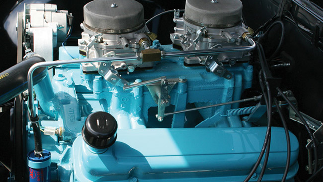
The 421 Super Duty package included a four bolt main cylinder block, Mickey Thompson forged pistons, heavy duty connecting rods, a McKellar #10 camshaft, heavy duty valve springs, deep
sump oil pan, special oil and fuel pumps, special harmonic balancer, air cleaner, flywheel, clutch, exhaust manifolds and a dual point distributor. Machine work on the Catalina’s current engine was performed by Nunzi’s Automotive and camshaft is a custom reproduction grind of a McKellar #11. Engine assembly was done by the owner.
|
|
Another interesting fact is that the dealer sponsor of record was not Cal Wible Pontiac, but Jack Shaw’s East Side Pontiac. Upon closer examination, this makes perfectly good sense since the Jack Shaw logo appeared on many winning drag cars of the time, including both Pontiacs and the Chevrolet of “Fast Eddie” Schartman. It appears that the Aluma Chief enjoyed a two year career as a drag car exclusively before being converted to street use and the anonymity it brings. The good news is that this rare and unique example of factory involvement in organized competition was not destroyed in a racing or towing accident, as were so many of its contemporaries. Having a relatively short racing career meant it was not extensively modified or cut up, and best of all, survived life in the Ohio rust belt throughout the decades.
The Aluma Chief was purchased by current owner Kenny Colacino in 1992. Being a long time Pontiac man and drag racer himself, Kenny kept the old warrior safe and dry until 2003 - all the while accumulating the parts necessary for a first class restoration. And one look at the results of Kenny’s labors reveals that he has turned the former drag car into a Best of Show winner, while showcasing the car’s racing roots by outfitting it with some of the rarest factory performance options ever to roll out of Detroit.
On a recent bright spring day I marveled at the Catalina’s flawless black paint gleaming in the sun, and watched this now seemingly huge car roll along with a period correct nose high attitude and seven inch wide “Cheater” slicks. I was transported back to 1963, and in my mind’s eye the Aluma Chief was on the starting line at Dragway 42 - preparing to dispatch yet another in a long line of lesser factory hot rods brought out to face her.
|
|
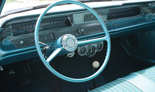 The basic Catalina Sport sedan has a Spartan yet tasteful interior. Simple two spoke steering wheel, vinyl bench seat and lack of radio and heater helped shave off pounds.
|
| |
|
|
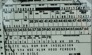 The Aluma Chief’s build sheet contains notations for assembly line workers to delete dum-dum insulation and install aluminum front sheet metal. Body in aisle informed workers where this special body was located when the chassis assigned to it came down the line.
|
You want Swiss with that?
It has been said that necessity is the mother of invention, and never was that statement more accurate than during the horsepower wars being waged between the auto manufacturers during the 1960s. It seemed like every week Ford, GM, or Chrysler was introducing another performance option to either lighten their cars or increase the horsepower output - and Pontiac was no exception. In spite of realizing great success with their 1962 aluminum-nosed Super Duty cars, Pontiac’s counsel in charge of performance recognized the need to step up the program even more if they hoped to stay on top in 1963. One area addressed was overall vehicle weight. Of course, in the case of drag racing, getting weight off the front end was most advantageous. So, in an effort to maintain parity with the cars being fielded by the Chrysler Corporation, Pontiac shed additional pounds from the ’63 Cats by stamping even thinner aluminum panels for the fenders and hoods (than they had for the ’62 models). Pontiac also built 14 all-out racing versions of the Catalina with radically lightened frames in 1963. Due to the factory having drilled large holes throughout the chassis, these cars came to be known as “Swiss cheese Catalinas”.
Another area that received improvement (not that it appeared any was needed) was in the 421 Super Duty engine for 1963. It received cylinder heads with larger ports, lighter valves, and improved valve springs. These were topped off by an improved intake manifold - while the beauty of it all was the fact that the advertised horsepower rating remained the same. All part of the game being played out on the street, dragstrip, and circle tracks by the Big 3 during those wonderful times when horsepower was king.
|
|
 |
|
Reverse flushing your cooling system, Part 2.
Last issue of Colin’s Corner, we presented Part 1 of how to properly reverse flush your car’s cooling system. Here’s part 2…
by Bill Carberry
The final things to check before starting the flush are that you put the radiator cap back on and the drain plug on the radiator is closed. Another very important thing to check is that if your car has a heater control valve it is now in the hot or open position. Failure to do this can cause excessive pressure build-up in your heater core which may very well cause it to leak.
|
|
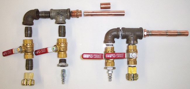
You can make your own flush gun for $25 to $30 and it can also
help wash the car and driveway later on.
|
Very slowly open the valve on your source of fresh water and make sure that you get fluid coming out of the top of the radiator. If you don’t, you either have a major blockage in the heater core, the heater valve is closed, or you have no water pressure in your hose. The fluid will come out whatever color it originally started out at and will gradually change to clear as all the old fluid is replaced with clean fresh water. Assuming you have good flow out of your system, you can now add just a little bit of air pressure (if you are using a flush gun like I have shown). I will repeat, just a LITTLE bit of air pressure. You only want to give it enough pressure to create some bubbling activity in the cooling system to help loosen up any sediment or blockages. Once again I cannot stress the importance of proper disposal of your old dirty coolant. Please check with your local municipality for the acceptable methods in your area.
|
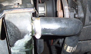
Rotate the upper hose to point down into a drain pan.
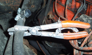
If you use a flush tee you will need to direct your flush in the right direction by crimping the hose.
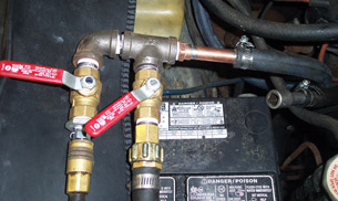
Flush gun hooked up, pushing in the water with a little bit of air pressure.
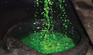
Catch the old antifreeze and dispose of it properly.
|
|
Fill ’er up.
Ok, now you have a cooling system that is free of all the old antifreeze and hopefully all or most of the other undesirable sediments that have accumulated over the years. Now you can disconnect your flush hose from the engine, but do not hook up the heater hose to the engine just yet. You also want to drain out as much of the clean water from the system as possible, so open the radiator drain plug to drain the radiator all the way down. After the radiator is empty and you have closed the drain plug (try not to forget this part) you can start putting in fresh antifreeze. But wait, the heater hose is not hooked up yet. No, I didn’t forget. If you leave the heater hose off the engine as you pour in the fresh antifreeze, you can eliminate most of the air pocket in the engine to make for an easier and quicker warm-up. When you see liquid just start to come up out of the open heater hose fitting, stop adding antifreeze and hook up the heater hose. Now you can fill up the rest of the way with antifreeze.
A little information here about antifreeze and the proper mix. Some people think that more is better - not so. Try to get as close as possible to a 50/50 mix. If you are in a climate with severely cold temperatures, you can go as far as 65% antifreeze and 35% water. Any higher percentage of antifreeze is a waste of money and actually detrimental to the cooling system for at least two reasons. Reason #1; at extreme cold temps a 100% mix of antifreeze will actually start to jell up sooner than a proper mix. Reason #2; pure antifreeze will not dissipate heat in hot weather as well as a proper mix. Think of antifreeze like oil. You have many different types of oil, right? What is the difference between gear oil and motor oil? Would you put motor oil in your differential or gear oil in your engine? Straight antifreeze would be too “thick”, kind of like gear oil and will not transfer the heat out of the system the same as a proper mix will. On the sample vehicle we flushed the cooling system capacity as specified in the owners manual: 14 quarts. This comes out to 3-½ gallons. Putting in two gallons of undiluted antifreeze will provide approximately a 60% antifreeze and 40% water mix.
|
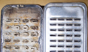
A clogged 4 row radiator core next to a new one. Regular maintenance will prevent or at least delay this from happening to your radiator.

This heater core was part of a cooling system that was not reverse flushed on a regular basis.
|
|
Fire when ready...
OK, the radiator is filled almost to the top, the heater hoses are hooked back up, and the drain plug is closed, right? Time to start up the engine. Right after start-up, the level in the radiator may drop down a bit. If so, bring it back up to just below the filler neck and wait for the thermostat to open up. Just prior to the thermostat opening the coolant may rise and fall a bit and maybe even push out. Once the thermostat opens, the level will drop and you can top it off. Since the engine will be warm/hot at this point, you should fill the radiator right to the bottom edge of the filler neck and put on the radiator cap. If your car has an overflow tank you should fill that at least ½ way up so that as the engine cools it can draw coolant from the tank. Most 1960s and older cars do not have a separate tank and should not be filled all the way to the top when cold. This lower level allows room for the coolant to expand and pressurize as the engine warms up. If you do fill one of these older cars all the way to the top when cold it will only push out the overflow until it finds its own level.
You have just performed a true reverse flush of your cooling system. Please remember that a cooling system flush is meant to prevent problems, not fix them. If your cooling system has been neglected and the radiator or heater core has become seriously clogged, a reverse flush probably will not solve your problem. A complete system flush every two years should prevent build-up in the system. Due to the many variations of different manufacturers cooling systems I may not have given a precise set of directions for your particular vehicle, but these steps should apply to most classic cars and trucks.
Source:
Bill Carberry
Classic Radiator
566 Fulton St (Rt 109)
Farmingdale NY 11735
|
|
 |
|
|
A Primer on Flywheels and Flexplates
Tools: standard socket set, flat-blade screwdriver, breaker bar, torque wrench
Cost: new flywheels will run you just over $300 (new GM), flexplates usually go for a little over $100. OPGI carries both for 1964-’77 Chevelle & El Camino.
Tinware: new ring gear plate, flywheel/flex plate bolts (optional), loctite
Tip: Be sure to research the right replacement part for your application. An improperly balanced rotating assembly will wreak havoc on the rest of your motor.
Performance gains: a stronger, properly-balanced rotating assembly
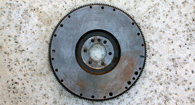
No engine would be complete or useful without the ever-important flywheel or flex plate. These large, ring-gear plates are mounted to the rear flange of the crankshaft at the back of the engine block. In conjunction with the starter assembly, the plates are responsible for “kicking over” the motor when the ignition is fired. Along the outer rim of the plate is a series of geared teeth designed to mesh with the pinion gear of the starter motor. When power is applied to the starter (via the ignition switch), the pinion gear engages the teeth of the flywheel/flexplate and turns the plate in the direction of rotation. Since the plate is bolted directly to the crankshaft, this quickly gives the motor its’ initial “breath of life” and gets things moving.
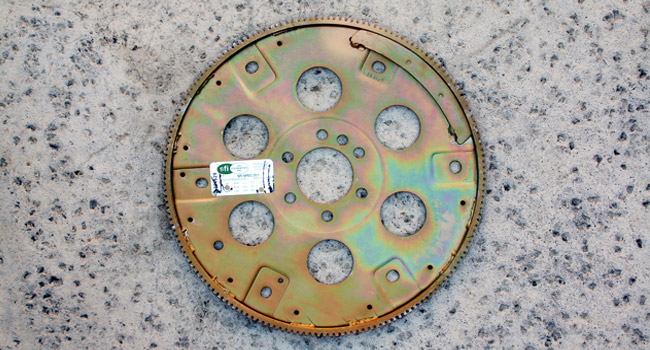
Although flywheels and flexplates are almost identical in function, they vary slightly in design. The face of a flywheel (above photo) has a smooth, machined surface similar to a brake rotor. This is strictly for the application of a manual clutch. The pressure plate of the clutch assembly is bolted to the outside ring of the flywheel. The pressure plate applies force to the clutch disc (located between the pressure plate and flywheel) when the clutch pedal is released. This connects the drive of the engine to the transmission and beyond.
|
|
|
A flexplate (above photo) however, is intended for automatic controlled vehicles. Since the torque converter aptly handles the transfer of power between the motor and the transmission, there is no need for the manual clutch and flywheel assembly. Instead, the flexplate mounts to the rear of the crankshaft (same as the flywheel) and simply serves as the mounting point for the torque converter. For this reason, flexplates are typically lighter than their flywheel counterparts.
Whether it’s automatic or manual, the removal of the plate is pretty much the same. The transmission must be disengaged and pulled from the motor in order to access the rear of the crankshaft. Remove the bell housing and clutch assembly (if so equipped). On automatic cars, the transmission case is a one-piece design. Removal of the torque converter from the flexplate is all that’s required.
Using a long breaker bar for additional leverage, loosen and remove the six retaining bolts and washers from the flywheel or flexplate. If the plate turns while attempting to remove the bolts, try wedging a screwdriver between the teeth of the plate and the starter gear to lock it into place. The threads of the bolts should be cleaned before reassembly. If any threads are damaged or marred, replace the bolts. A set of new ARP bolts will cost you about $25-$30. Closely inspect the surface of the flywheel and the condition of the teeth. If the surface indicates excessive wear in one particular area of the plate, you could have a misaligned clutch assembly. If the gear-teeth are chewed-up or broken, you may need to correct the engagement of the pinion gear to the flexplate. This can be done using starter shims.
When it comes to replacing the flywheel/flexplate, it can be a little tricky. Different displacement motors often came equipped with different plates. This is most evident in the number of teeth on the outside ring of the plate. The diameter can vary as well. Measure the diameter of your existing plate and count the number of teeth present on the ring (usually 153 or 168). This will ensure you make the correct replacement.
In addition to the size and teeth issue, you also need to consider the way in which the motor is balanced- internally or externally. An internally-balanced crankshaft should be balanced without the flywheel/flexplate or the vibration damper attached. These external components have a “neutral” balance in the equation and allow for greater interchangeability. This means an aftermarket flywheel or damper can be installed without throwing the engine’s balance out of whack.
On the other hand, an externally-balanced crankshaft requires the added components for proper balancing. These cranks are manufactured with lighter counterweights—relying on the external weight of the flywheel and damper to make up the difference. Once the pieces have been balanced as a package, any part change will require rebalancing of the entire assembly.
Some machine shops actually convert externally-balanced cranks into the more-desired internally-balanced pieces. This is done by adding material to the crank to achieve the “correct weight”. The conversion is not cheap, but it may be worth the extra effort for hassle-relief alone.
After the right plate has been selected, the installation is self-explanatory. Reverse the steps listed above and torque all bolts to the recommended settings. Apply a liberal amount of loctite to the threads before assembly.
|
|
 |
|
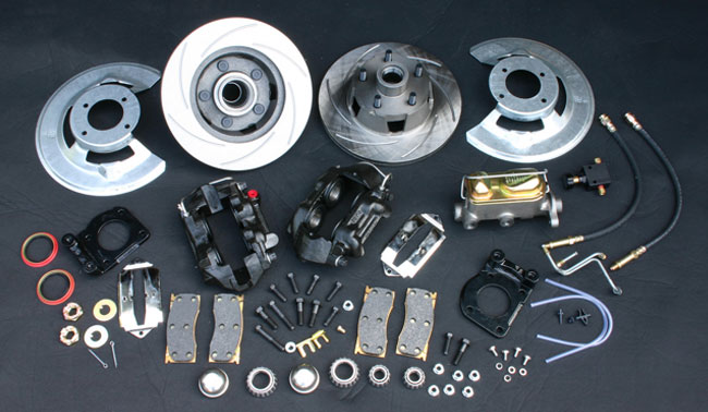
Many disc brake kits come complete with everything you possibly need
to improve your car’s braking performance
.
|
|
Installing front disc brakes
Tools: standard socket set, standard wrenches, floor jack and jack stands, rubber mallet, ball joint separator or pickle fork, mini sledge
Cost: will vary depending on the components and kit level of quality used; typically anywhere between $500-$1500. OPGI has front and rear disc brake kits available for all years of GM A-Body.
Tinware: disc brake kit, wheel bearing grease, brake fluid, brake cleaner, small rubber hose, “catch” container
Tip: A much-overlooked detail in the disc brake conversion is the placement of the wheel by the hub assembly. Often times, the mounting plane of the new hub will cause the wheel to sit further outward in the wheel well. Depending on the wheel and tire size, this slight variance can create all sorts of clearance problems. Check it out before installing or assembling the parts!
Performance gains: Disc brakes are far superior to the age-old design of drums. They stop faster, last longer, and greatly improve the agility of your vehicle.
Today, disc brakes are a staple in the performance game. Anybody who still runs hard
with the ancient, 4-wheel drum theory is seriously lacking. Let’s face it—the stopping power is simply not there. And we all know what that feels like. Being forced to jam on the binders in a tight situation can be fatally scary! Drum brakes require a much longer skid pad (similar to that of an airplane landing strip) to finally bring the car to a halt. They are also highly vulnerable to brake fade from excessive heat and water. Truth is, we often get so caught up in horsepower and the endless pursuit of going faster- that we simply forget at some point we have to slow down.
Well, the only safe and effective way to harness big power is with the addition of disc brakes. Although discs require greater pressures between the pad and the rotor than those required on drums, they offer superior stopping resistance and handling under heavy braking. With discs, you also have the option of upgrading to larger-diameter rotors and calipers to further improve control. Keep in mind you may need to switch to a larger wheel to accommodate the new and improved rotors. Be sure to check your clearances beforehand. If you’re working off a budget and simply can’t afford the higher dollar items, vented or slotted rotors and carbon-metallic pads offer better-than-stock braking performance at an affordable price. In addition, they also keep the rotor and pad surface cleaner, lower operating temperatures, and improve wet braking.
Since most of the stopping force derives from the front wheels (approximately 60%-70% on rear-wheel drive cars), it goes without saying that the forward units should be addressed first. Front disc brake kits are packaged and sold in various stages of completion, and range anywhere from $500 to $1500. It really just depends on what you need. Some kits are all inclusive with rotor assemblies, calipers and pads, master cylinder/power booster, and all of the necessary hard lines to adapt to your particular application. Other kits take a more bare-bones approach.
Let’s get down to business. Remove the front wheels from the car. By now, everyone should be familiar with proper jacking and support techniques. With the wheels removed from the hub assemblies, gently pry the grease cap from the front of the hub. Next, remove the cotter pin, the castle nut and washer, and the outer wheel bearing from the spindle. Be sure to keep track of your hardware and the order in which it was removed. The old hub and drum are now free and clear for dismissal. It may be necessary to retract the shoes from the drum linings using the adjuster slot in the drum’s backing plate. Insert a small flat-blade screwdriver into the slot and back off the adjusting screw. If the drum continues to put up a fight, it may take a little “coaxing” from a rubber mallet to get things moving.
At this point, I recommend draining the brake fluid from the system. Start by using a siphon to draw out as much fluid as possible from the master cylinder reservoir. Attach a small hose to the bleeder screws and allow the remainder of brake fluid to be drained from the master cylinder and the brake lines into an empty container. Remove the soft brake hoses from the wheel cylinders as well. Be careful not get brake fluid on any painted surface. The stuff is nasty and will eat the paint right off.
As I mentioned before, there are numerous different brake kits for all different cars. Although it’s not uncommon for some manufacturers to include replacement spindles as a part of the package, some kits are designed and intended to reuse your existing drum spindles. The step-by-step sequence may vary greatly depending on your selection of parts and the kit that best suits your needs. Follow the manufacturer’s instructions first and foremost during the procedure.
In our case, we were able to reuse the factory drum spindles. However, we opted to remove them anyway for cleaning and re-painting. Using a pickle fork and a mini sledge hammer, we separated the tie rod and the ball joints from the spindle assembly. If preferred, the drum and hub assemblies may be removed from the vehicle as one complete unit without the disengagement of the steering knuckle. This is entirely up to you. Simply unbolt the backing plate from the spindle assembly and remove the unit as a whole.
If you purchased a fully assembled kit, the rest is pretty straightforward. Attach the knuckle assembly to the control arms and tie rods, and re-fasten the lines and hoses. Although our kit came unassembled, it was pretty straightforward in its own right. After the fresh paint on the knuckles had dried, we installed the supplied spindle brackets and the new backing plates. Thoroughly grease and install the new inner wheel bearings into the hub/rotor assembly. It is highly important to keep the bearings clean and free of all dirt and debris. The bearings can be lightly tapped into place with a clean, rubber mallet or large socket. Be careful not to damage the lip or the seal of the bearing while doing so.
The freshly-packed rotor may now be installed onto the shaft of the spindle. Install the outer bearings and again, grease heavily! The spindle nut and washer should be loosely fitted over the bearing, but not tightened. The calipers may be assembled and installed onto their designated rotor. Once the unit is complete, mount the spindle assembly back into the car and torque the bolts to the proper spec. To seat the outer wheel bearings, torque the spindle nut to approximately 15 lb-ft while spinning the rotor. Back off the nut 1⁄2 turn, retighten, and install a new cotter pin and grease cap. Refill the system with the recommended brake fluid and bleed thoroughly.
As with any aftermarket kit, be prepared for the unexpected. Fabricating new hard lines is not uncommon with a disc brake swap. Neither is relocating or re-plumbing a proportioning valve. There are many factors to consider before laying down the plastic and ordering a new kit. It’s always a good idea to call the tech-support lines prior to purchasing and pick their brain on any gray areas. Each kit will most likely be different in one way or another. Always follow their instructions to the letter.
|
|
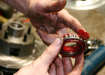
It’s important to heavily grease the bearings before installation.
|
|
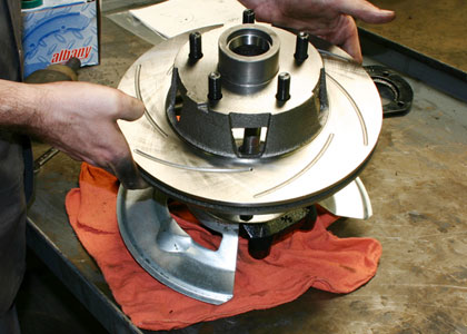
Install the rotor assembly onto the shaft of the spindle as shown.
|
|
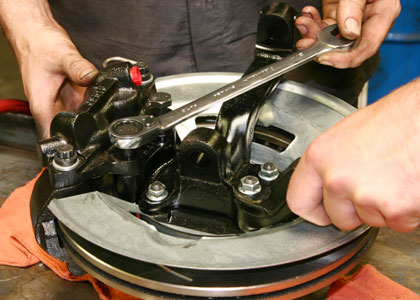
The caliper is secured to the caliper mounting bracket with grade 8 bolts and lock washers.
|
|
|