|
The Mighty Rochester, Part 2
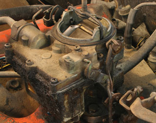 Earlier this year, in a past episode of Colin’s Corner, we focused on the Rochester Quadrajet. Yes, the mighty four-barrel carburetor that came affixed to the top of just about every high-performance GM V8 engine. Well, there were other versions of the Rochester carb – specifically the 2-barrel and the 6-barrel incarnations—both of which left their mark over the years.
|
|
2-barrel
The Rochester 2G carburetor was introduced in 1955, and was used in various applications by all GM divisions through 1979. It is easily identifiable by the words “2 Jet” on the air horn (lid). This carburetor was made in two base sizes. The original “early” size has center to center stud dimensions of 2” x 3-¼”, and a bore size of 1-7/16”. The larger base stud dimensions are 2” x 3-¾”, with a bore size of 1-11/16”. In all, 5 cfm (cubic feet per minute) sizes were produced, ranging from 278 cfm to 435 cfm (see chart for details). The difference in cfm allowed the versatility of this unit to be factory installed on smaller engines such as the Chevrolet 265 and 283 cubic-inchers. The largest 2Gs were used on the Chevy 400 and Pontiac, Olds, and Buick 455 engines in the early ’70s.
By designation, there were three versions of the “2 Jet”.
• 2G has a manual choke.
• 2GC has an integral choke assembly with black choke cap.
• 2GV has a remote mounted choke assembly (on the intake manifold)
with a vacuum pull-off.
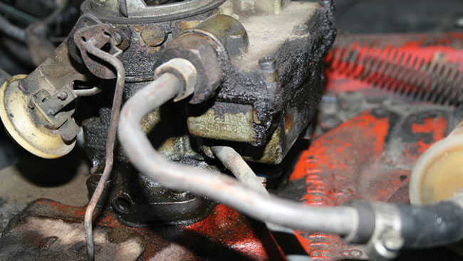
This is the original Rochester 2G that used to perch atop the intake of our ’69 Buick Special.
The best part of the whole deal is all that grease - it preserved the carburetor and protected
it from rust, corrosion, and various and sundry maladies.
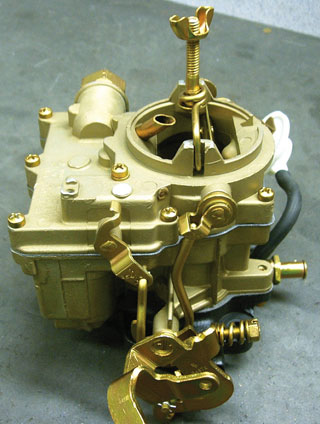
Saving the 2G
Our Rochester 2G (2-barrel) unit. The carb was torn down, inspected, cleaned, electroplated using the zinc dichromate process, then reassembled.
Our Buick’s 2-barrel was also recalibrated for using today’s unleaded gas, and checked for problems like hesitation, flat spots, hard, hot starting, etc.
|
|
|
|
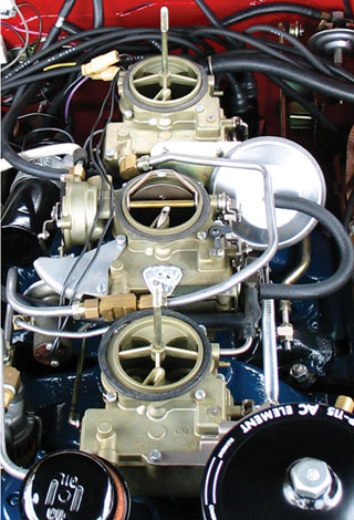
Triple 2-barrel
Whether you call it a tri-power, a six pack, or triple two-barrels, multiple carburetion is considered a high performance package. Even if they do run poorly, the “eye candy” appeal under the hood is unmistakable. Like most multiple carburetion, the Rochester 2G carburetors in this application do not work very well. In an effort to keep tuning simple for service technicians, only the center carburetor was made with an idle circuit. A person only needs to adjust the two idle mixture screws, just like any other two or four-barrel single carburetor. The problem with this is that the two outboards still leaked air around the four throttle plates, and no matter how precision-aligned they were, a lean air/fuel mixture was delivered to the front and rear cylinders. This resulted in a rough idle.
A second problem exists with the triple two-barrels. On all but a few Pontiac and Olds manual transmission applications, the outboard carburetors are opened by a large diaphragm. The driver has no direct control of the opening.
|
|
Venturi vacuum is supplied to this diaphragm through a vacuum slider switch. The system works on the speed of the air going through the center carburetor. By producing venturi vacuum, and at higher throttle positions, the two outboard carburetors open. The problem is not with the system, but with the drivers and mechanics who simply do not understand the system’s workings. They typically remove the vacuum diaphragm and the slider switch and then fabricate various “manual” linkage apparatuses to open the outboards. Not professional engineering by any stretch, and you can only imagine the complications arising here!
Overall, the 2G carburetor is adequate. It’s not an awesome performer and does not get particularly great gas mileage. It has proven to be very reliable though—a bulletproof carburetor that has withstood the test of time.
| Rochester Carburetor Flow Ratings |
CFM |
| Quadrajet: Air flow at 90º air-valve opening |
|
| 1-3/32-in. venturi (primary) |
750 |
| 1-7/32-in. venturi (primary) |
800 |
| |
|
| Dualjet |
|
| 1-3/32-in. venturi |
227 |
| 1-7/32-in. venturi |
287 |
| |
|
| Varajet (staged 2 barrel) |
|
| 28mm primar |
375 |
| 30mm primar |
397 |
| |
|
| Model 2G: 1-1/4-in. flange, 1-7/16-in. throttle bore |
|
| 1-3/32-in. venturi |
278 |
| |
|
| Model 2G: 1-1/2-in. flange, 1-11/16-in. throttle bore, |
|
| 1-3/16-in. venturi |
352 |
| 1-1/4-in. venturi |
381 |
| 1-5/16-in. venturi |
423 |
| 1-3/8-in. venturi |
435 |
| |
|
| Model 4G: Throttle bore & venturi size in inches |
|
| 1-7/16 – 1-1/8 primary; 1-7/16 – 1-1/4 secondary |
486 |
| 1-7/16 – 1-1/8 primary; 1-11/16 – 1-15/32 secondary |
553 |
| 1-9/16 – 1-1/8 primary; 1-11/16 – 1-15/32 secondary |
692 |
| |
|
| Monojet |
|
| 1-7/16-in. throttle bore, 1-7/32-in. venturi |
160 |
| 1-11/16-in. throttle bore, 1-5/16-in. venturi |
210 |
| 1-11/16-in. throttle bore, 1-1/2-in. venturi |
250 |
| |
|
NOTE:
4 barrels rated at 1.5-in.Hg pressure drop.
2 barrels rated at 3.0-in.Hg pressure drop.
1 barrels rated at 3.0-in.Hg pressure drop.
|
|
|
|
 |
|
GM A-Body quiz: The Answers!
Last month, we put out our second quiz on Colin’s Corner. This one was A-Body-specific, unlike the “general” General Motors quiz earlier this year. Here are the answers to the 10 questions posed. (I hope you didn’t cheat using the Internet for all your answers, but even if you did, I’ll bet you at least had some fun!)
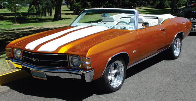
GM A-Body quiz:
1. Name 3 of the North American plant facilities in which GM A-Body vehicles were manufactured (there were 6 in total)
(Freemont CA, Atlanta GA, Baltimore MD, Framingham MA, Kansas City, MO, Oshawa Canada)
2. Name 3 Pontiac A-Body models that were produced during the ’60s and early ’70s.
Bonus question: in 1971, which Pontiac A-body name was dropped, and what new name replaced it?
(Tempest, LeMans, GTO. In 1971, the Tempest was dropped and the T-37 became the replacement)
3. The GM A-Body platform eventually morphed into a front wheel drive version. What years was it a rear wheel drive platform?
(1964-1981)
4. What year were GM-A Bodies allowed to employ more than 400 cubic inch engines?
(1970)
5. Name the two station wagons that were built on the A-Body platform (in the 1960s and early ’70s) that used stretched wheelbases and raised rear roof sections with skylights.
(1964-1972 Oldsmobile Vista Cruiser and the 1964-1969 Buick Sport Wagon)
6. What were the largest cubic inch engine displacements ever offered in the Chevelle, GTO, Cutlass, & Skylark?
(Chevelle: 454, GTO, Cutlass, Skylark: 455)
7. What body style was the Chevrolet El Camino based on?
(Chevelle Station Wagon)
8. Name the high performance versions of the Chevrolet, Pontiac, Oldsmobile,
and Buick A-Bodies.
(Chevelle SS, Pontiac GTO, Oldsmobile Cutlass 4-4-2, Buick GS/GSX)
9. Was the 1970-72 Monte Carlo officially classified as an “A” Body?
(The Monte Carlo & Pontiac Grand Prix were both extended variants of the A-Body,
officially called a G-Body)
10. The A-Bodies manufactured between 1964 and 1972 were all based on the same GM corporate platform, but shared very little in the way of major body components and panels. Name one major item that was common to all A-body divisions.
(The windshield)
We’ll do some more of these quizzes from time to time. Keep an eye out right here at
Colin’s Corner!
|
|
 |
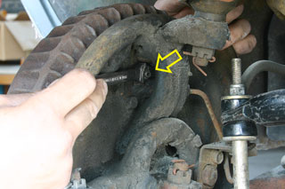
Slowly open the bleeder valve on the backing plate to drain the fluid
Bleeding brakes
Tools required: standard wrenches, vacuum bleeder or pressure bleeder (optional, but recommended)
Bleeding your brakes is never a fun thing to do. Instead, it’s a tedious, patience-testing process that can often takes numerous attempts before getting it right. Thorough bleeding of the brakes is an absolute must when it comes to performance and safety. When air pockets form in the brake lines, the pedal becomes soft and spongy.
This is due to the fact that air is more easily compressed than fluid.When the pedal is mashed, the trapped air compresses and expands much like a spring. In turn, the air absorbs the energy from the pedal and prevents the delivery of fluid to the brake caliper.
The act of bleeding involves filling the lines with fluid and removing any trapped air pockets or bubbles from the brake system. Although there are different approaches to bleeding, they all share the same common goal and result.
Tip: When working with brake fluid, always be super-careful. Brake fluid can quickly and permanently ruin paint jobs. Even a slight film on your hands can leave its mark on the car. It’s a good idea to wear rubber gloves and cover all painted surfaces around the master cylinder reservoir.
The most straightforward and effective method of bleeding is done manually. Before the introduction of vacuum and pressure bleeders, there was just one way in which to properly bleed the brakes—the hard way! The only drawback of manual bleeding is the need for a second set of hands (or feet, actually). With an assistant at the pedals, the bleeding is performed by hand at each wheel—one at a time. By depressing and pumping the brake pedal, fluid rushes through the system at a high velocity rate. Air bubbles and trapped particles are quickly flushed from the system by the flow of fluid.
To bleed manually, attach a small rubber hose to the brake caliper nipple. Route the opposite end of the hose into a container to catch the fluid. With your auxiliary pair of feet, firmly pump the brake pedal a few times—holding the last stroke of the pedal down to the floor. With the pedal depressed, slightly loosen the nipple to allow the pressurized fluid to exit the system. The fluid should come rushing out, so be careful. It’s not a bad
idea to wear some safety glasses. However, if the fluid slowly dribbles out the end of the hose, chances are the lines are clogged with contaminants. Check the condition of all brake lines and hoses before moving forward. At this point, it’s critical to maintain pressure on the pedal. Premature release will only permit air back into the lines. Simply tighten the nipple and allow the pedal to return.
Another option in the bleeding game is to reverse the strategy and use a vacuum bleeder. They attach to the caliper nipple and draw the fluid through the lines from the master cylinder. These bleeders are extremely easy to use and perform fairly well. It’s best to perform a “final bleed” manually after vacuum bleeding (and pressure bleeding). Sometimes air can still be trapped in the system, even after numerous bleeds.
An alternative method to bleeding the brakes is to use a hand-held bleeding device or tool.
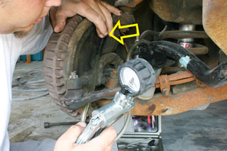
The vacuum bleeder attaches to the valve and draws the brake fluid through the system from the master cylinder.
The pressure-style bleeder works in a similar fashion to manual bleeding. The kits usually attach to the top of the master cylinder and pressurize the fluid out of the reservoir and through the system. Take the same approach at the wheels to release the fluid from the nipples. Pressure bleeders are effective in eliminating air pockets from the lines and are relatively inexpensive (approximately $50). The cool thing is you can easily bleed the whole system single-handedly without the help of an assistant.
Regardless of the method used, always start the bleeding process at the wheel farthest from the master cylinder—working your way back to the left front wheel. This will help minimize the air in the system. It’s also beneficial to bleed each caliper more than once. Working your way around the vehicle several times can be quite time consuming, but the more you bleed, the better you brake—plain and simple. Be sure to keep an eye on the reservoir and fluid level as you bleed. If the reservoir begins to run dry, you start sucking air back into the lines. At this point, you don’t want to start over!
|
 |
|
How to properly reverse flush your cooling system, Part 1.
by Bill Carberry
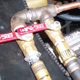 Many people seem confused as to the best way to flush out the cooling system in their classic car or truck. Most folks agree that reverse flushing is the best way to go about it, but may not know how to achieve a true reverse flush. Reverse flushing will tend to push out most debris that builds up in coolant passages, especially those of the radiator and heater core. I will try to explain in the simplest terms how get the desired results.The layout of components that I am using in this procedure will be consistent with what will be found in most vintage V8 engines and even most 4 and 6 cylinder applications.
Go with the flow
Let’s start with how the antifreeze/coolant mixture goes through your cooling system under normal operating conditions. The easiest place to start (and also to remember the flow pattern), is to realize that heat rises. Hot fluid will leave the engine at the thermostat housing. On most classic vehicles this is the highest point on the engine, except of course for the carburetor. From the thermostat housing the fluid goes through the upper radiator hose to the radiator. This may seem rather simple and basic to most of you, but please be patient while I go through the motions anyway.
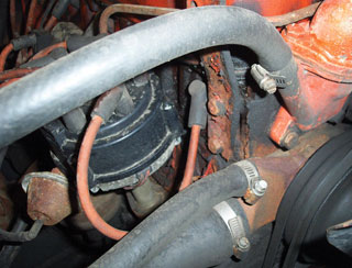
They should all be this simple. Heat comes out of the engine near the thermostat housing to go to the heater core. Coolant returns to the engine at the water pump.
Once in the radiator, the fluid gets cooled off as it passes through the core portion of the radiator. This is the part with the tubes and fins. Heat transfers from the fluid, to the tubes, to the fins, and the fins get cooled off by the air passing through the radiator. After being cooled off, the fluid is then sucked back into the engine by the water pump. It is at this point that a lot of people are not sure which way the fluid flows.
The water pump actually pushes the fluid through the engine block from front to back. In fact, there are many head gaskets that have small or no coolant passages in the front of the gasket just for the purpose of forcing the coolant to the rear of the block.
Once at the back, the fluid goes up to the cylinder head and starts to go back to the front of the engine through the heads themselves. On a typical V8, the fluid from both heads will then flow together again in the front of the intake manifold and out the thermostat housing to start the journey all over again.
Since the fluid is at its hottest at the thermostat area, this is also the best place to tap into to the circuit for some much needed heat in the cold winter months. Most manufacturers have the hose that feeds the heater core start very close to the thermostat, but not all do - so you may need to think and search a little if yours is not the norm. And remember, you can always go back to the basic scientific law that heat rises. As the fluid goes to the heater core it may or may not go through a heater control valve. This varies from car maker to car maker and even model to model from the same car maker. Once the fluid is in the heater core it actually acts as a miniature radiator and cools off the fluid by transferring the heat from the fluid to the air that passes through it. Only this time we want that heated up air to warm up our fingers and toes. After the fluid has gone through the heater core and lost most of its heat, it gets sucked back to the engine through the heater return hose to the water pump. Yes, just like the radiator gives up its coolant to the water pump, so does the heater core. Again, this description applies to most common V8 engines because I need to stick to something that most of you are familiar with without getting into a description of how newer vehicle’s cooling systems are designed.
Shifting into reverse...
Okay, now that we know how the normal flow of things goes, we can do some preventive maintenance on our pride and joy by throwing it in reverse. It would be best to start this procedure when the engine is cool, so you don’t waste time going to the emergency room with some serious burns. Draining the cooling system of its existing coolant is the best place to start, but not really required.
Of course, you should drain it into a drain pan for proper disposal. But do be sure that there is no pressure in the system. Now you should remove the heater return hose from either the water pump or the heater outlet tube. You will want to go into either the hose or the heater core so that you are forcing water to go backwards through the heater core.
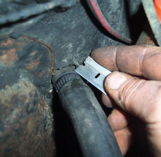
Better to slice the hose and replace it than create a leaking heater core.
If you choose to remove the hose from the heater core be sure to use extreme caution so you don’t create the problem of a leaking heater core. Slicing the hose and peeling it off the heater neck will usually assure no heater core problems. In fact, now might be a good time to replace the heater hoses anyway.
There are many “Reverse Flush Kits” for sale in just about every auto parts store and most might work just fine. I use a home-made flush gun that combines water and air pressure to force the fresh water into the system and all the old stuff out. If you disconnected the hose from the heater core, you will need a scrap piece of hose to connect from the flush gun to the heater core.
If you took the heater return hose off at the water pump, just put the flush gun into the hose and clamp it with a hose clamp. Now you need to block off the opening just created by your flush gun hook-up. Any simple thing will work since it is only temporary. You can even stick an old spark plug in the hose and clamp it if you have to.
Exit strategy
Now that you are ready to push all the old fluid out, you need to give it an exit. Let’s go through the system backwards and see where we end up. Through the heater core (backwards), into the engine near the thermostat housing, backwards through the cylinder head(s) and engine block to the water pump, out the lower radiator hose and into the lower neck of the radiator. The fluid will then go backwards through the radiator tubes and come out the top neck of the radiator. This is where all the old stuff will come out. We have now gone backwards through the heater core, engine and radiator. This is a true reverse flush. Remove the upper radiator hose from either the upper neck of the radiator or at the thermostat housing. If you choose to leave the hose connected to the radiator, you might want to rotate it so it points down into a drain pan to catch the old stuff. As far as the other opening, you won’t need to do anything as long as there is a thermostat in place and it is closed, as it should be with a cooled off engine. The closed thermostat will prevent your flushing procedure from turning into a messy bath for you. If the thermostat is stuck open, now would be a good time to change that too. If you don’t use a thermostat for whatever reason, you will need to plug up the housing to prevent the aforementioned bath.
Stay tuned! We’ll have the rest of our reverse flush story in next month’s CC!
|
|